Light-Me-Up Tiles
|
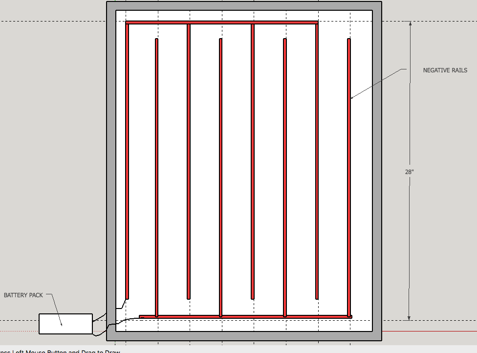
Light-Me-Up Tiles are unique, personalized LED-lit scenes. They can be made out of a variety of materials and are intended for beginners to design and assemble by hand. Magnetic strips are used to hold the tiles to a metallic whiteboard and facilitate the electrical connections. In addition to being a mounting surface, the whiteboard also provides the 3V DC power to the tiles by means of a set of copper tape "rails". The tiles are illuminated when placed correctly on the board. Tiles are easily removed, and can be powered by a 3V coin cell battery to be displayed individually.
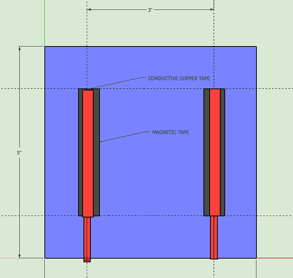
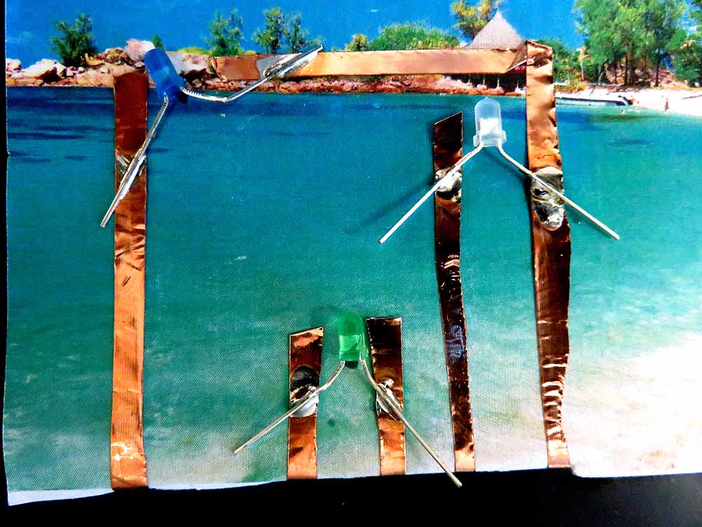
The base of each tile is a 5" x 5" square of lightweight material such as chipboard or corrugated plastic[ 'coroplast']. On the back are 2 magnetic strips, spaced 3" apart like the power rails on the whiteboard. Several LEDs are embedded into the scene, either readily visible or such that they shine through thin material. The LEDs are connected in a parallel circuit using copper tape, then soldered to the copper tape. The positive and negative conductors from the circuit fold over to the back of the tile and over the magnetic strips, ready for contact with the power rails. The magnets hold the tile to the board and help make a secure electrical connection. |

|
|
Materials for Mounting Board:
|
Whiteboard for 20 tiles
|
Materials for Tiles:
- Lightweight material that does not tend to warp, such as chipboard or corrugated plastic
- Magnetic strips, 1/2" wide, adhesive backing, flexible
- Craft materials such as origami paper, tissue paper, pipe cleaners, markers, scissors
- Hot glue guns and glue sticks- low temperature
- Copper tape with conductive adhesive, 1/4" wide, as used for mounting board
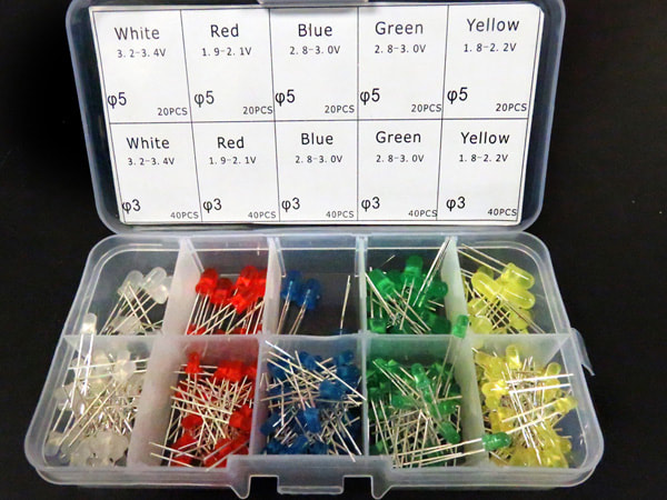
- LED assortment Choose LEDs with colored plastic so they can be identified easily
- Soldering station, solder
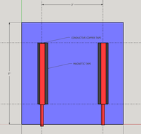
Magnetic strips on back of tile
|

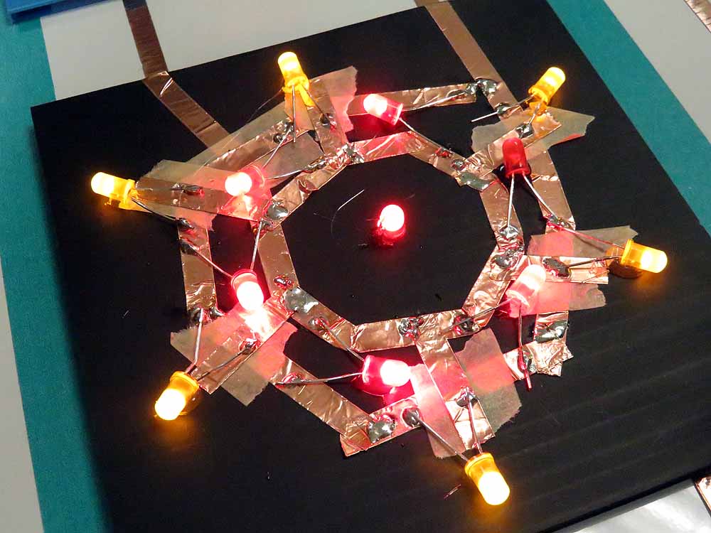
Example Illustration(Iron-Man Arc Reactor) used to layout LED locations
|
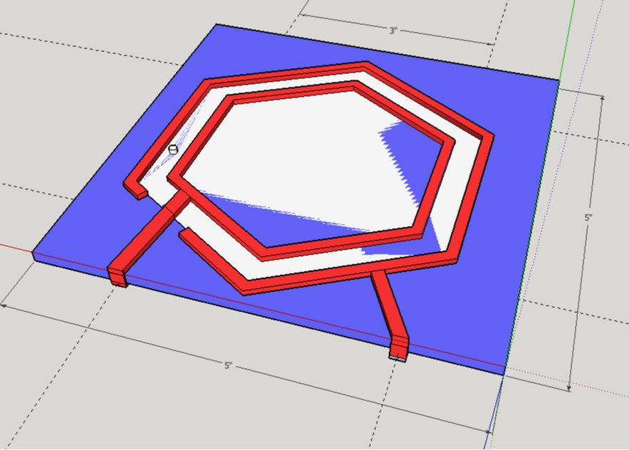
Parallel circuit on front of tile- used to power ring of LEDs for arc-reactor design
|
|
Instructions:
- Create a powered mounting board as specified on this drawing.
- Create blank tiles with magnetic strips.
- Cut the blanks to be approximately 5" x 5"
- Add magnetic strips, approximately 3" long, spaced 3" apart, on the back of the tiles as shown in the drawing below.
- Mark the + and - sides
Create the scene:
- Design the scene on separate paper
- Choose LEDs that require a similar voltage to turn on (usually specified on the package).
- LEDs come in two "families": 2V and the 3V. Red-yellow family LEDs will turn on with 2V, whereas blue-green-white family LEDs require 3V to turn on. If LEDs from the 2 families are mixed, for example Red and Green are wired in parallel, only the low voltage LEDs will turn on. (This can be fixed by using a small resistor in series with the low voltage LED, but it’s easier just not to mix).
- Create the scene using craft materials.
- Based on the design, mark locations for LEDs on the tile.
- Secure the LEDs to the tile using hot glue. !Be careful to only glue the plastic, not the wires - they will be soldered and the glue can ruin the solder joint. LEDs can lay on their sides, or face straight out. They can also be pushed through the tile, in which case electrical connections will be made on the back of the tile.
|
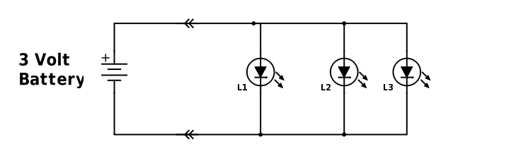
Example of light-me-up tile schematic diagram. Additonnal LEDs can be added in parallel.
|
The LED's in the light-me-up tile form a parallel circuit, as shown above- each LED has the full 3 volts applied to it. Note that if a power source greater than 3 volts is used, a current-limiting resistor should be used in series with each LED.
- Create the circuit
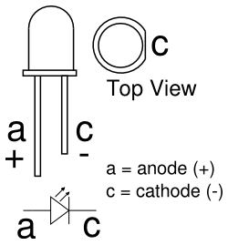
- Identify the positive (+) and negative (-) ends of the LEDs and note it on the tile. (+) is the longer leg. Another way to identify the negative end is by a small flat on the plastic head of the LED.
- Layout the parallel circuit by drawing with pencil. Connect all the (+) ends together and run them to the (+) strip on the back of the tile. Connect all the (-) ends together and run them to the (-) strip on the back of the tile. The (+) and (-) can cross, but an electrical insulator will be needed.
- Make the circuit using copper tape. Tape can be laid over other tape to continue or turn an electrical path. Run a fingernail or pencil point over the place where two pieces of tape meet to ensure a good electrical connection. If (+) and (-) need to cross, then cover the bottom conductor with a piece of masking or electrical tape to insulate it from the other conductor.
- Test the circuit. Use the powered board or an individual battery pack to test the circuit before it is soldered. You will need to hold the LED legs onto the copper tape, and may need to test each LED individually. Fix the circuit as needed.
- Solder the LEDs to the copper tape.
- Test the circuit and debug as needed.
- Complete the scene as desired.
- Share all LightMeUp tiles with the group!
Electronics concepts:
- Circuit principles - insulators and conductors, series and parallel circuits, positive and negative
- Circuit components- light-emitting diodes(LEDs),anode and cathode
- Wiring materials- copper tape
- Soldering
- Debugging
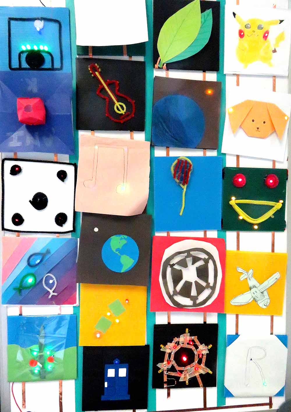
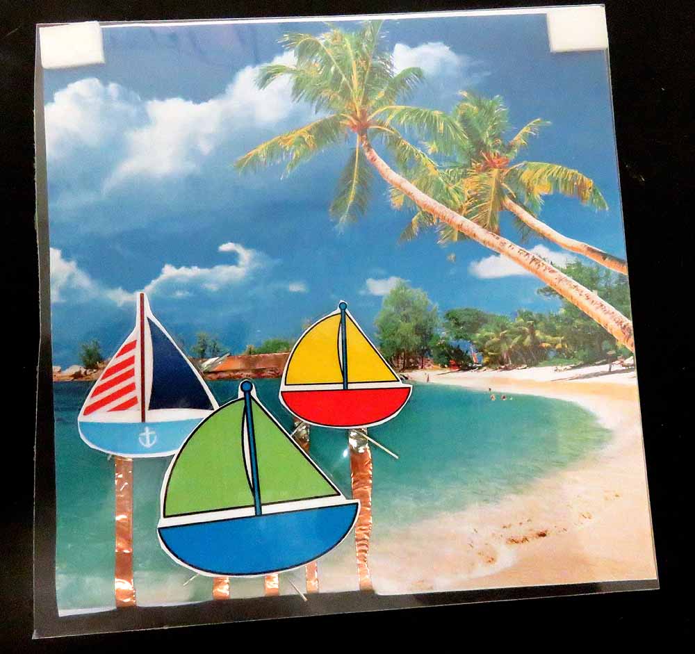
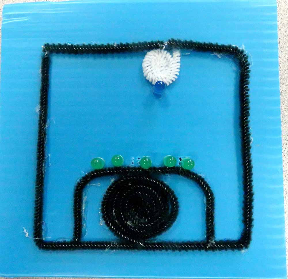
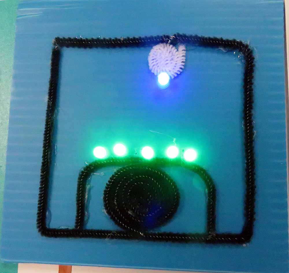
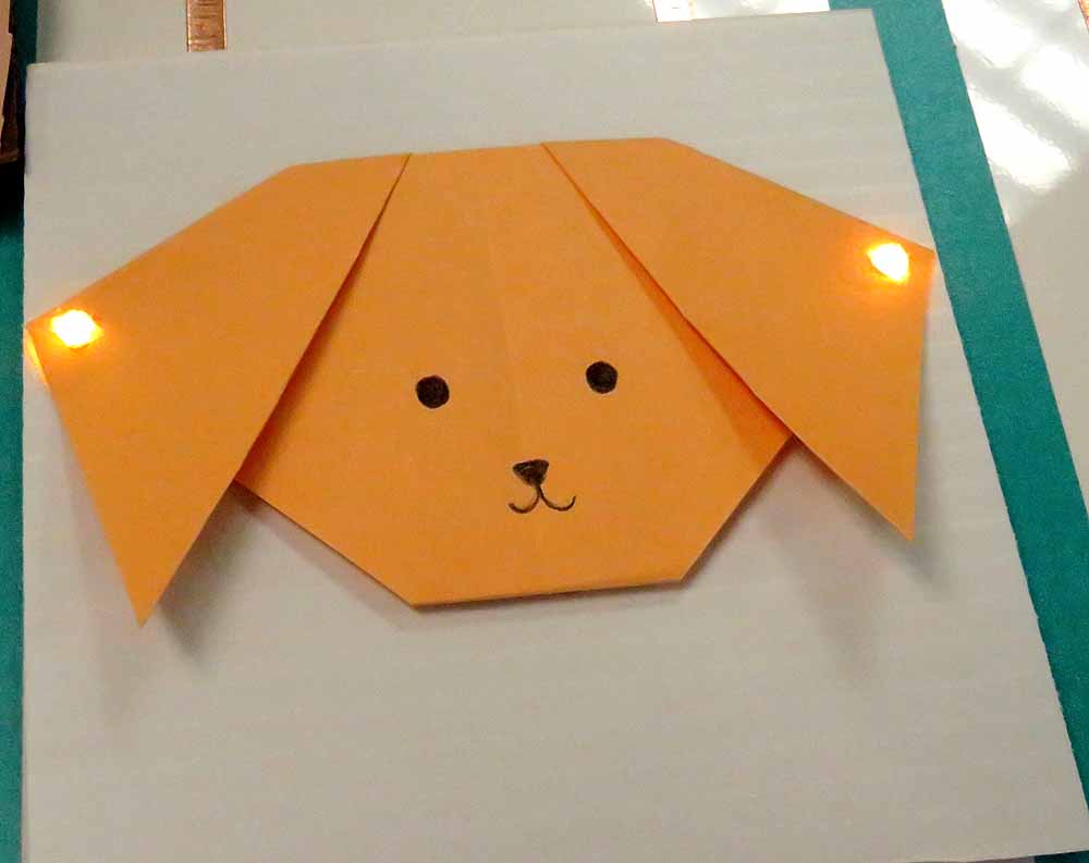
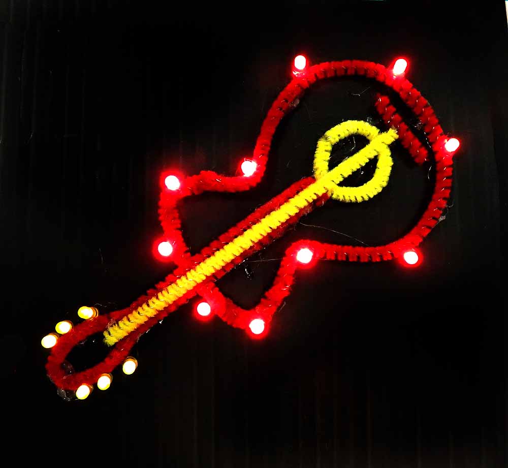
Examples of finished tiles:
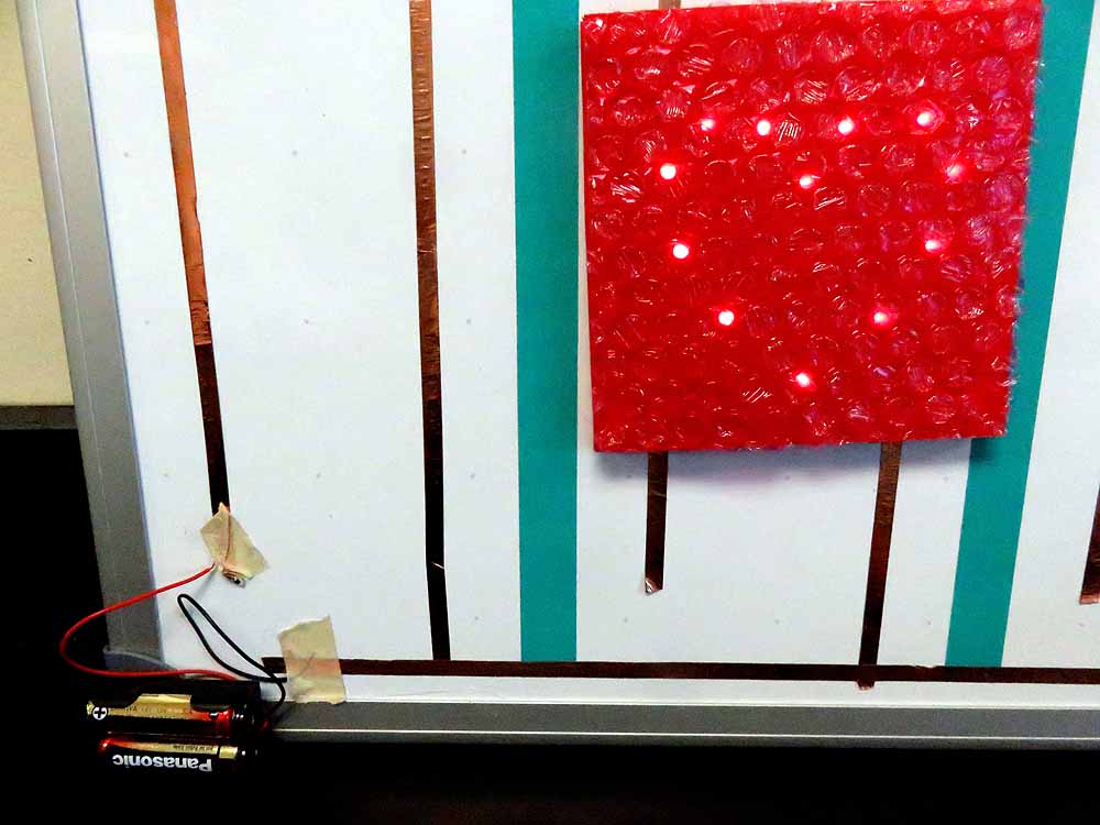

Examples of finished board: