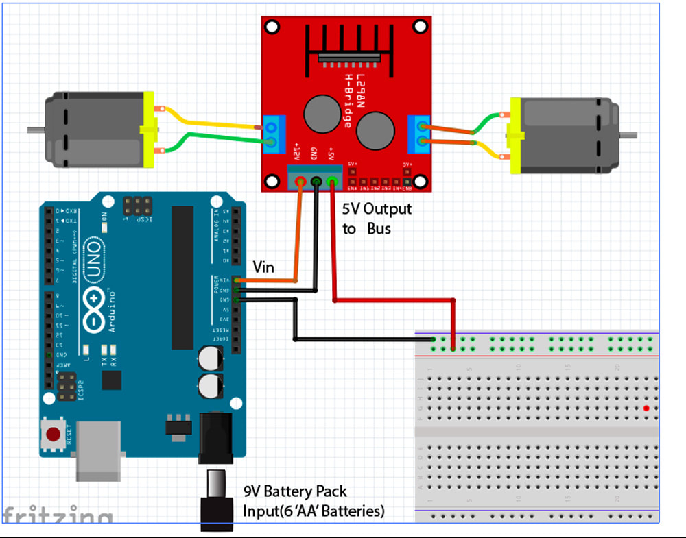
Robot Power Wiring
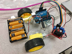
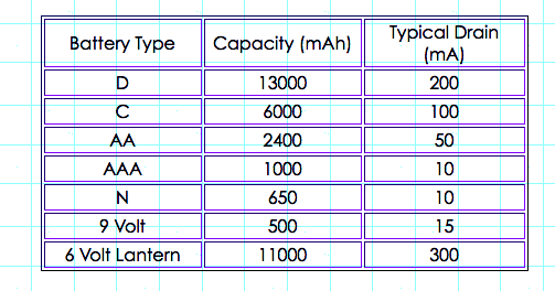
9V Battery Pack: The robot is powered by a 9V battery pack consisting of six (6) 'AA' batteries in series, which can supply more current for a longer time than a single rectangular 9V battery.
Arduino Power: The 9V battery pack is suitable for the Arduino which expects an input voltage of 7V to 12V.
Arduino Power: The 9V battery pack is suitable for the Arduino which expects an input voltage of 7V to 12V.
Motor Controller Power:
the L298N motor controller board is used to powers the motors. It uses an "H-bridge" which can run the motors in either direction.
The DC Motors draw more power than the Arduino can supply directly (approximately 50 mA to 200 mA each). The 9V power into the Arduino is routed to the Motor Controller board by connecting the Vin pin on the Arduino to the +12V pin on the L298n board.
L298N H-Bridge Tutorial
The direction of each motor is controlled with logic signals from the Arduino, and the motor speed is controlled with a PWM signal from the Arduino to the Enable pin for that motor.
5 Volt Power for the Sensors and Lights
In addition to powering the motors, the L298N is able to supply enough power at 5V to the power bus on the breadboard to power all the various sensors and lights. Connect the +5V and GND pins on the L298n Motor Controller board to the power and ground bus on the breadboard that is used for the sensors and lights.
Note: This means that the Arduino must use the 9V power source to get valid sensor readings even if it is being powered through the USB cable from the computer.