Robot Wiring
Robot Wiring List (pdf) View/Download
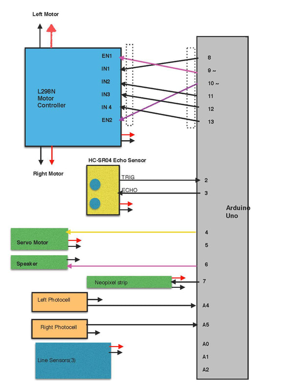
Wiring Rationale:
Motor Control: We wanted to pick six pins together. The enable lines need PWM pins( marked with a tilde(~), so we attached these to pins 9&10.
That leaves pins 8 & 11 for the direction pins for Motor 1, and 12&13 for the direction pins for Motor 2.
Ultrasonic(HC-SR04): This needs two digital pins. Pins 0 & 1 are reserved for the serial link-otherwise they must be disconnected everytime you send or receive serial data. So we choose pins 2&3 for trigger(outgoing pulse) and echo(incoming pulse)( plus 5V power and ground buses).
A Servo Motor could connect to any digital pin, so we choose the next pin-pin #4( plus 5V power and ground buses).
The Speaker or buzzer(if used) could connect to any unused digital pin( plus ground bus).
The Neopixel strips can connect to any unused digital pin( plus 5V power and ground buses).
If using analog photocells, these could connect to any one of the analog pins, A0 through A5(plus 5V power and ground buses).
The QTR analog line sensors(6 total), should connect to the six analog input pins A0 through A5 (plus 5V power and ground buses).
