Motor Control Using L298N H-Bridge
DC motors cannot be connected directly to the Arduino for several reasons:
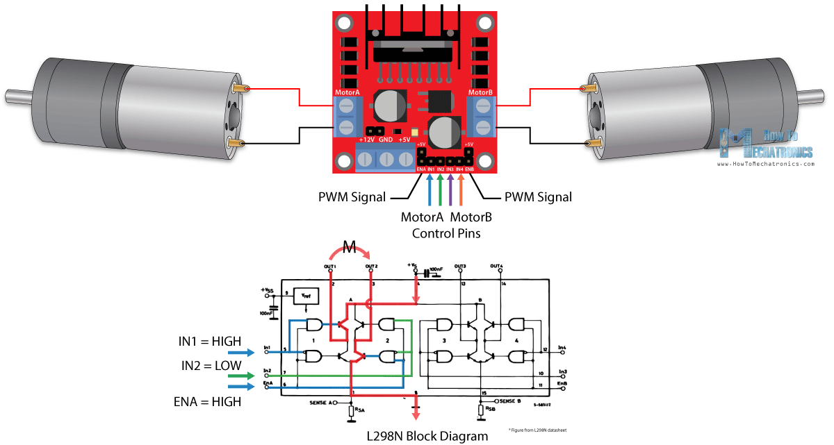
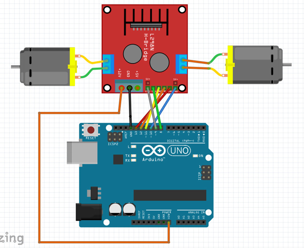
These shortcomings are resolved by using the Arduino to control an H-bridge motor controller such as the L298N.
The motors are connected to the motor output pins on the L298N- pins 1&2 and 13&14 on the diagram below.
Motor Speed
Pins 7 & 12{Enable 1 and Enable 2) are used to control the motor speed. They can either be jumpered to 5V for the motors to always run at maximum speed, or can be connected to pulse-width modulation(PWM) output pins on the Arduino(pins 3,5,6,9,10, and 11) which are marked with a tilde(~). See more info below.
- The Arduino pins cannot supply enough current to drive motors
- The Arduino pins cannot supply enough voltage to drive most motors
- The Arduino cannot drive motors in both directions
These shortcomings are resolved by using the Arduino to control an H-bridge motor controller such as the L298N.
The motors are connected to the motor output pins on the L298N- pins 1&2 and 13&14 on the diagram below.
Motor Speed
Pins 7 & 12{Enable 1 and Enable 2) are used to control the motor speed. They can either be jumpered to 5V for the motors to always run at maximum speed, or can be connected to pulse-width modulation(PWM) output pins on the Arduino(pins 3,5,6,9,10, and 11) which are marked with a tilde(~). See more info below.
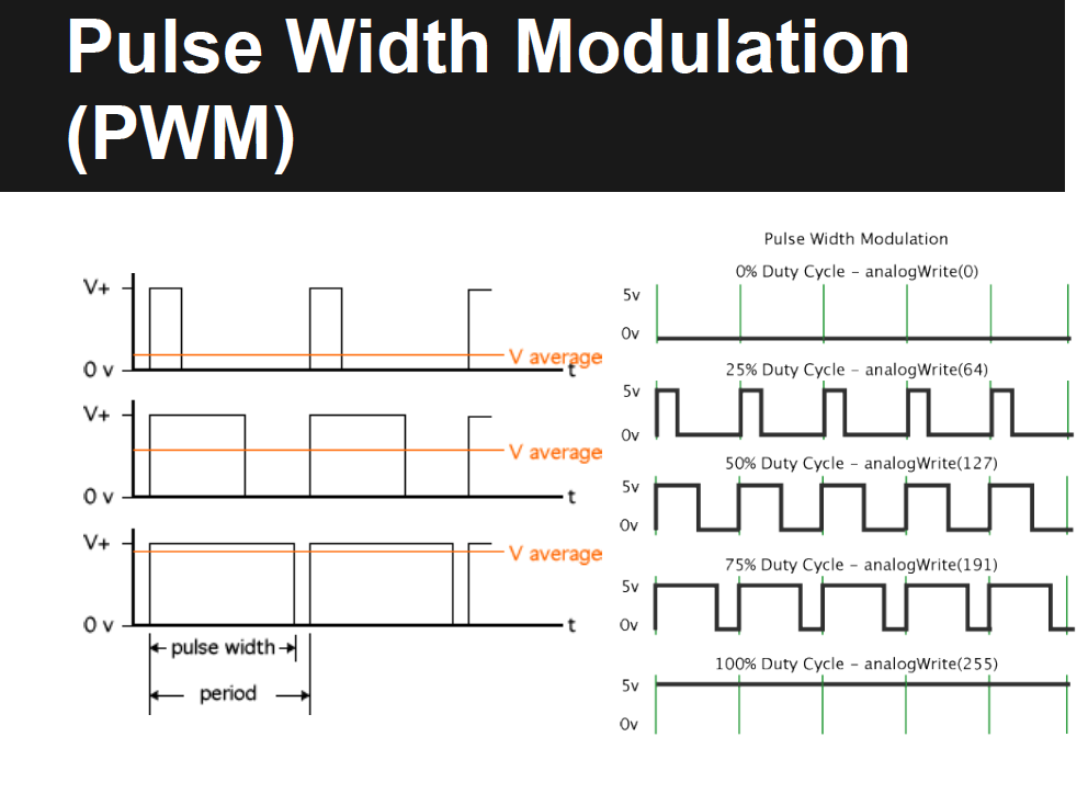
Speed is controlled by doing an analogWrite of between 0-255 to the selected enable pin. If your sensors create values outside this range, use the map function or constrain to make them come out right.
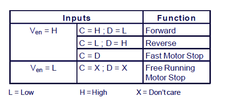
Motor Direction
Motor direction is controlled by digital logic signals supplied by the Arduino to Pins 8&9( IN1 and IN2) and to Pins 10&11(IN3 and IN4). If the logic level of 8=9 or 10=11, the motors stop.
Motor Direction
Motor direction is controlled by digital logic signals supplied by the Arduino to Pins 8&9( IN1 and IN2) and to Pins 10&11(IN3 and IN4). If the logic level of 8=9 or 10=11, the motors stop.
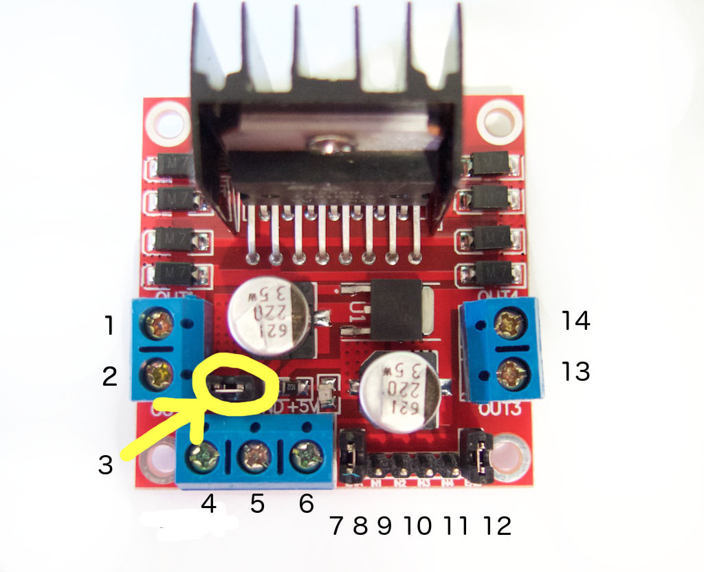
- DC motor 1 "+" or stepper motor A+
- DC motor 1 "-" or stepper motor A-
- 12V jumper - remove this if using a supply voltage greater than 12V DC. This enables power to the onboard 5V regulator
- Connect your motor supply voltage here, maximum of 35V DC. Remove 12V jumper if >12V DC
- GND
- 5V output if 12V jumper in place, ideal for powering your Arduino (etc)
- DC motor 1 enable jumper. Leave this in place when using a stepper motor. Connect to PWM output for DC motor speed control.
- IN1
- IN2
- IN3
- IN4
- DC motor 2 enable jumper. Leave this in place when using a stepper motor. Connect to PWM output for DC motor speed control.
- DC motor 2 "+" or stepper motor B+
- DC motor 2 "-" or stepper motor B-
The Arduino cannot output a true analog voltage, i.e., one that varies continuously from 0 volts to 5 volts.
Instead, using the analogWrite( pin#, val) function, where val ranges from 0 to 255, it outputs to pin# a square wave signal of varying duty cycle, from 0 to 100%, which continuously varies the power sent to the motor.
Instead, using the analogWrite( pin#, val) function, where val ranges from 0 to 255, it outputs to pin# a square wave signal of varying duty cycle, from 0 to 100%, which continuously varies the power sent to the motor.
Simple Motor Test Program
// Left motor pins-by defining them here, we don't have to keep stating pin numbers, making future rewiring much easier
#define ENA 9 // ENA speed pin for left motor
#define IN1 8 // IN1 on Motor controller board
#define IN2 11 // IN2
// Right motor pins
#define ENB 10 // ENB speed pin for right motor
#define IN3 12 // IN3 on Motor controller board
#define IN4 13 // IN4
int rightspeed = 150;
int leftspeed = 150;
//----------------------------------------------------------------------------------------------
void setup() {
pinMode(ENA, OUTPUT); //set up left motor
pinMode(IN1, OUTPUT);
pinMode(IN2, OUTPUT);
pinMode(ENB, OUTPUT);//sets up right motor
pinMode(IN3, OUTPUT);
pinMode(IN4, OUTPUT);
analogWrite(ENA, leftspeed); //set speed to mid
analogWrite(ENB, rightspeed); //set speed to mid
}
void loop() {
digitalWrite(IN1, HIGH);//left motor forward
digitalWrite(IN2, LOW); //
digitalWrite(IN3, HIGH);//right motor forward
digitalWrite(IN4, LOW);
}
